Frequently Asked Questions
| While this winch does produce a moderate amount of noise, here are a few things that may help: 1. The most common cause of a loud squealing noise is that the motor is held too tightly to the large drive gear. You should be able to loosen the motor plate and adjust the motor so it isn’t quite so tight to the large drive gear. 2. You can lubricate the gears with lithium grease, being careful not to get any on the clutch brake. Once a year use 30 weight motor oil on the cable. Refer to your owner’s manual for complete instructions. 3. Install sound deadening pads between the winch mount and trailer. |
Check the weight of your top. The weight capacity is 1200 lbs.
Several things could happen as a result. Restricting the top while the winch is activated is likely to cause damage to one or more gears, or could cause the motor gear to be sheared off. Replacement parts can be ordered in the store.
The folding camper winch has a 40-amp breaker. At 12-volts, the maximum watts will be 480-watts. Typically, the winch will draw around 25-30-amps depending on the camper top that is being raised. This would be anywhere from 300-watts to 360-watts. It is always best to size things for the maximum current which can be up to 40-amps. Current draw is always dependent on the load being driven. In this case, the weight of the camper top.
The most common cause is that when setting the limit switch, the lower limit was not set first. See the manual for instructions on setting the limit switch. If the top was able to be raised and lowered previously and just stopped lowering, it may be that the limit switch or the relay pack needs to be replaced. Usually the relay pack would be the part that has failed if everything worked before, then one direction suddenly stopped working.
You will need to set both the upper and lower limits, beginning with the lower. It may take up to 100 turns to get the adjustment set correctly. See manual for full set of instructions.
This is usually the pinion gear coming loose from the shaft. If the motor is turning but the gears are not, this is likely the problem.
The part you need is P92001. P55012 is the part number created for the camper manufacturer for this same model.
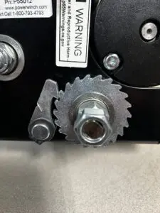
It is likely the pawl is not latching into the ratchet gear properly. This is usually caused when replacing the clutch and/or ratchet gear. The bearing only fits in the gear in one direction. If the ratchet gear bearing is inserted from the wrong side, the gear will only fit on backward which makes the direction of the teeth incorrect. Please review the photos and ensure your gear is inserted properly.
If the camper top will only go in one direction no matter what you do in adjusting the limit switches, it may be that the relay pack has failed and only one relay is working.
This is likely due to worn thrust washers and/or bearings. Replacement part# P7160901AJ.
This is likely due to worn thrust washers and/or bearings. Replacement part# P7160901AJ.
First, make sure the clutch lining is clean and free of grease. If so, it is likely the clutch bearing insde the 120-tooth gear has failed. Replacement part# R1001 (For models RC23, 712, RC30, 912) or R1018 (For model 915)
The folding camper winch has a 40-amp breaker. At 12-volts, the maximum watts will be 480-watts. Typically, the winch will draw around 25-30-amps depending on the camper top that is being raised. This would be anywhere from 300-watts to 360-watts. It is always best to size things for the maximum current which can be up to 40-amps. Current draw is always dependent on the load being driven. In this case, the weight of the camper top.
This is likely due to worn thrust washers and/or bearings. Replacement part# P7160901AJ.
No, all electric trailer winches have the same mounting footprint and hole pattern. See mounting templates for a printable version.
With the clutch knob loosened, run the motor and pull cable out at the same time. If this did not work, use a hammer to tap on the shaft where the emergency hand-crank goes. If the cable is still not moving, make sure the cable is not kinked or wound around itself. Note: The cable must be pulled tight while winding. Any slack in the line can cause the cable to kink or wind around itself.
Engage the motor for a few seconds with the clutch fully released. This should free the clutch and allow the cable to be pulled out.
Yes. An older model with a silver motor can be replaced as well, but has a slightly larger collar beneath the motor gear. This will require grinding approximately 1/32″ off the inside of the frame yoke to allow proper seating and alignment of the mounting holes.
You can find this 5 amp standard fuse at any automotive supply retailer.
There could be several causes. Try these steps to isolate the trouble:
1. Ensure there is sufficient power from the vehicle’s battery. If the battery is not fully charged, the winch may not have sufficient power to operate.
2. Confirm all points of connection to battery, winch, circuit breaker, switch, etc. are tight and clean.
3. Check for bare wires or signs of wear that could cause a short.
4. Check circuit breaker at battery.
–Bypass the circuit breaker and test the winch. If the winch runs, the circuit breaker needs to be replaced. If the winch does not run, reconnect the circuit breaker and continue with trouble isolation. NOTE: DO NOT operate winch without circuit breaker. Removing circuit breaker from the circuit is ONLY for testing.
4. Check in-line fuse.
–A 5amp, 250Vstandard automotive AGC glass type in-line fuse is located under the top cover of the winch. If the fuse blow immediately when power is applied, disconnect wire harness from winch and batter and check polarity of wiring in connector. Correct as needed.
–Use the 3 screws to take apart the plug and check to make sure the positive line from the battery is going into the gold terminal inside plug.
5. Check wiring.
–Check to make sure wiring is correct from switch to socket to motor. (Does not apply to model 915)
6. Apply 12v power directly to motor leads to ensure motor is functioning. See Diagram
7. Make sure you are using the correct wiring harness hooked directly to a 12v battery. The stock trailer plugs on many vehicles WILL NOT support the Powerwinch.
8. Check the control module wiring and ensure it is correct.
9. Check the control module for signs of failure.
This is due to slack in the cable when winding. Ensure the cable is pulled tightly while being wound. Any slack in the line can cause the cable to kink or wind around itself prohibiting cable movement. Also ensure the angle of the line is centered on the shaft, and check that the level wind plate is not missing, damaged, or installed incorrectly.
A blown fuse is likely the result of reversed polarity of the wires in the power cord connector. Follow these steps:
1. Disconnect the power cord from the winch and battery.
2. Remove the cover from the plug.
3. Check the cable for the ribbed side of the flat cable. The ribs indicate the negative or ground conductor.
4. Check to see if the ribbed side of the flat cable is connected to the silver terminal in the plug.
5. If not, disconnect and swap the wires.
6. Make sure the ribbed conductor is connected to the silver terminal and the smooth conductor is connected to the gold terminal.
7. Replace the plug cover.
8. Replace the fuse if blown.
9. Reconnect the power cable to the bttery making sure the breaker is connected to the + on the battery.
10. Plug the power into the winch and test.
A clicking sound is usually the signal of a bad solenoid or control module inside the winch. Remove the cover to determine which component is causing the sound. Replace solenoid or control module using diagrams.
You don’t need to. The circuit breakers have automatic resets after several minutes.
NOTE: ALWAYS use correct rated fuse. Using wrong fuse can cause winch to not operate and/or cause damage to electrical components.
An in-line fuse is located under top cover of unit. In-line fuse is a standard automotive AGC glass type fuse. Required rating is 5A, 250V. Fuses are available at local automotive parts stores.
To access fuse:
1. Disconnect wire harness from winch.
2. Remove four (4) T-30 torx drive screws that attach top.
3. Lift top up. Use care to not break or damage wires.
4. Locate fuse holder and open to inspect/ replace fuse.
5. Test operation of winch.
If fuse blows when power is applied, check the polarity of wires in the wire harness connector.
1. Disconnect wire harness from winch AND battery.
2. Test continuity of the wires:
Using a continuity tester, place one probe in negative terminal of connector. Touch the second probe against vehicle frame.
3. If there is no continuity, remove cover from plug.
4. The smooth wire goes to gold terminal (+). Ribbed wire goes to silver terminal (-).
If connector is wired correctly (step 4), but there is no continuity (step 3), harness is defective and must be replaced.
Yes! You can use 6 gauge wire in place of the standard 8 gauge.
Our winches use the standard 3-hole mounting pattern. There is also a centerline pattern provided on the base plate.
You can connect directly to the negative terminal of the battery.
Usually the onset of a sudden, loud squeal means a bearing is failing. It may continue to work, but the noise will get progressively worse until the bearing is replaced.
The wiring harness you are using may be wired into the plug backwards. The black dual wire is marked. The ribbed side should be the negative and connected into the silver terminal in the plug. The smooth side is the positive and should be connected to the brass terminal.
The breaker on the wiring harness is becoming weak and beginning to fail. This should be replaced.
If the clutch plate has become stuck to the clutch pad the winch will not allow the cable to be released. Make sure the clutch plate is free from the clutch pad on the 120-tooth gear. You may need to clean off the clutch pad or clutch plate if there is debris or a substance present causing the two to stick together. You can also use the emergency hand crank to help release the cable.
NOTES: *ALWAYS use exact Powerwinch replacement cable. The winch rating and cable strength are matched for safe and optimum performance.
*NEVER replace cable with parts not approved by Powerwinch.
*ALWAYS wear leather gloves when handling cable. Steel cable can cause serious damage to hands.
1. Unplug wire harness from winch.
2. Loosen clutch knob (turn counterclockwise) and pull hook out completely.
3. Cut old cable off approximately 2” from drum shaft.
4. Slide collar away from cable then push old cable out of drum shaft.
5. Insert new cable through shaft. Cable must be inserted through side opposite counter bore.
6. Insert stop sleeve over end of cable until cable is flush with end of stop. Solder or crimp stop onto cable.
7. Pull cable back through shaft until stop is seated in counter bore of hole.
8. Slide collar around cable. Notch on the collar fits around cable.
9. Tighten clutch knob, turn clockwise until finger tight to set brake. DO NOT over
tighten clutch knob; over tightening can cause damage to clutch.
10. Reconnect wire harness to unit. Power- in cable, keeping tension on cable as it is winding.
Yes, BUT the strap has a weight capacity rating of 2000 lbs. This is ideal for use with our model 712 and RC23. If you want to use the strap in place of cable on any other winch, you will need to derate the weight capacity of your winch to 2000 lbs.
For wireless, remote-capable models (RC23,RC30), a manual override switch is present on the back of the winch. Follow these steps to override remote operation for boat retrieval:
1. Connect power to winch. Wire harness plug goes into socket on right side of winch.
2. Align boat and trailer.
3. Loosen clutch knob, turn counterclockwise and free-wheel cable/strap to boat. Attach hook to the eye on boat.
4. Tighten clutch control knob clockwise until finger tight to set brake. DO NOT over tighten clutch knob; over tightening can cause damage to clutch.
5. Press down and hold manual override switch. Power in cable /strap until boat touches bow stop. Release switch.
6. When fully loaded, secure boat to trailer.
An emergency hand crank is provided with your winch and can be used for manual operation when there is no power. The crank is stored in the left-hand side of the winch cover. Follow these steps to use the emergency hand crank:
NEVER USE HAND CRANK WHILE MOTOR IS RUNNING! ALWAYS REMOVE ALL TOOLS USED FOR MANUAL OVERRIDE OPERATION BEFORE OPERATING WINCH WITH ELECTRICAL POWER.
1. Disconnect wire harness from winch.
2. Remove outer nut from shaft on side opposite clutch knob.
3. Remove emergency crank handle from storage position and place on shaft.
4. Secure handle to shaft with nut removed previously. Tighten nut snugly against handle.
5. Tighten clutch knob, turn clockwise until finger tight to set brake. DO NOT over tighten clutch knob; over tightening can cause damage to clutch.
6. Turn crank handle to wind in cable. Clockwise for RC30, counterclockwise for RC23.
7. After boat has been secured on trailer, remove handle from shaft. Replace nut on shaft and tighten firmly against inner nut.
8. Place handle in storage position. Make sure handle is firmly seated in storage position before traveling.
Routine maintenance is essential in keeping your winch in proper working order. The following steps should be performed at least once per year.
NOTE: *ALWAYS disconnect wire harness from winch before attempting to install, service or perform any maintenance on unit.
Cable: Lubricate cable with Whitmore’s Wire Rope Spray, WD40 or equivalent. Spray shaft and cable as cable is being wound.
Gears: Remove covers and lubricate gears with a lithium based grease. Be careful not to get grease on clutch lining.
For optimum performance, remote should be operated within 10-15 feet from winch.
Check remote battery. Battery must provide a minimum of 9V to correctly transmit to the receiver. If it does then the battery is good move onto reprograming. If not, replace the battery.
To reprogram remote/receiver, check in the owners manual here. If the steps do not work, the transmitter or receiver is defective and should be replaced.
The calculation to determine your max anchor weight is: Anchor weight, plus rode/rope/chain weight, plus any additional hardware weight should be equal to or less than the pulling power of the unit. For example – using the Sport Fish 450 with pulling capacity of 450 lbs., and a rode and hardware weighing 47 lbs. Multiply the pulling capacity by 1/4 (450 x 1/4 = 112). Subtract total weight of all equipment (112 – 47 = 65) The total weight of your anchor should be equal to or less than 65 lbs.
The 80amp circuit breaker is a thermal breaker that should reset itself once it cools.
It is likely that the motor gear has spun off. Apply a small drop of red-loctite to the shaft and re-thread (threaded side goes toward motor) gear and let dry 36 hours before use.
Apply a small drop of red-loctite to the shaft and re-thread (threaded side goes toward motor) gear and let dry 36 hours before use.
This could be attributed to:
1. Incorrect wiring size. For Sport Fish 450 and 36 class windlasses, a minimum of 8 gauge wire should be used. For the 41 and 46 class windlasses, a minimum of 6 gauge wire should be used.
2. A bad motor. Apply 12v power directly to motor leads to ensure motor is functioning.
3. A bad or faulty switch. The 36, 41 and Sportfish 450 all use the P7817800AJ switch (4 terminals). The 46 class uses the P1028200AJ solenoid with the PO1019300AJ switch (3 terminals)
A couple of things to check:
1. The spin off gear is stuck and needs to be broken free. The spin off gear may over extend the threads and become stuck on the shaft. Older models were built with a leather washer which acts as a shock absorber for the spin off gear. It is designed to prevent the spin off gear from going to far towards the aluminum plate. If this washer becomes entangled with the spin off gear repeatedly, please replace this with the newer, neoprene washer.
2. The anchor weight is not enough to free fall. If this is the case, the you can opt for a heavier anchor, or employ a self launching bow roller to assist the free fall.
In most cases, the threads in the motor plate where the locking gear bolt goes through are stripped out. The motor plate will need to be replaced to repair this.
This either indicates that the rope is too soft, or the wrong rope size is being used. The Sport Fish 450 and Class 36 require 1/2″ rope and Class 41 and 46 require 5/8″ rope. We recommend using only Powerwinch rodes as they are manufactured using New England, premium 3-strand nylon.
The 36, 41 and Sportfish 450 all use the P7817800AJ switch (4 terminals). The 46 class uses the P1028200AJ solenoid with the PO1019300AJ switch (3 terminals), The wiring diagrams are shown here, and can also be found in the owner’s manual. Note: Wires from the straight prongs go to the winch and the diaganol prong wires go to the battery.
While the wiring harness is not supplied by Powerwinch, replacement circuit breakers are available. See requirements below:
1. The Sport Fish and Class 36 require a 25 amp circuit breaker and 8 gauge wire.
2. The Class 41 requires a 25 amp circuit breaker and 6 gauge wire.
3. The Class 46 requires a 60 amp circuit breaker and 6 gauge wire.
Yes, only for the Class 36, 41, 46. You will need part# The Sport Fish 450 is not compatible with a second switch. You will need solenoid part# P1028200AJ, and for a Class 36, you will need to change to 6 gauge wire.
This is likely a stripped locking gear. This is a difficult repair and may require a service center. You may be able to remove the locking gear from the stripped hole in the motor plate, and move it to another threaded hole above it. This is only if you can unthread it our of the plate. If you cannot, you can order another locking gear and put it in the empty hole and leave the stripped one there. The new locking hear will do all the work and it won’t hurt for the stripped one to stay in it’s orignal place.
No, all previous models do not have the same footprint as current models.
It is likely due to the motor wiring being reversed. Try reversing the wiring to correct.
This is likely due to the gypsy drive gear having been inserted incorrectly. Ensure the beveled side of the gypsy drive gear is positioned away from the plate.